This article is the text of a talk given by Andy Andrews to Bliss Probus Club in February 2011, at the Chequers Public House, Goddard Lane, in Chipping Norton, Oxfordshire. Andy was 99 in August 2011 and is still going strong. His original handwritten manuscript was transcribed by Kenneth Crawford in March 2012.
John Logie Baird was born in Helensburgh, Scotland, in 1888 and died in June 1946. He was Superintendent of Clyde Valley Electrical Power Company until the end of the First World War. In 1920, because of very poor health, he went to Trinidad and opened a jam factory.
He returned to England in 1924 and in very broken health went to Hastings and commenced his experiments in television. He invented stereoscopic television, also Noctovision — picturing what is seen in darkness.
In 1928 headline news was made when Baird televised images from Britain to the liner 'Berengaria' in mid-Atlantic
As you probably know, the earliest television and indeed, the first, was made possible by Baird, the Scottish engineer who adopted a purely mechanical/physical approach to his earliest experiments and later on, realising that mechanical scanning as such could never attain a speed commensurate with “flicker-less” pictures, turned to electronics, which eventually became the accepted method of scanning, transmitting and receiving pictures.
At this stage, perhaps a short explanation of TV as presented at the time may be helpful to those of you who are not quite as old as myself! Television relates to the transmission of wireless communication of visual representations of images and their reproduction at a distance.
In March 1925 Baird demonstrated “shadow images” for three weeks at Selfridge's store in London and in 1926 he gave the first ever demonstration of true TV by reflecting light from an image onto a photoelectric cell — a ginger head on a flexible stand.
The weakness of the apparatus was that at each moment it only utilised the light falling on the single point and then being scanned. He overcame this weakness by using a “mirror drum scanner” in the light projector which scanned the subject — which was in darkness — with an intense spot of light, thereby enabling an ordinary photocell to serve as a pickup device. This became known as the Spotlight transmitter.
This was the basis of the Baird 30 line system as used in the late 20s and early 30s, and the receiver called “ the televisor “ was designed around those principles.
Perhaps we may like to consider at this point – what makes TV work? Remember that we saw earlier that TV is the transmission or sending of a moving scene or pictures by radio waves.
A radio wave can be likened to a ripple in water after throwing a pebble into a pond with a skimming action, an activity which I am sure most of us have indulged in. The wave ripples the water in all directions, moving it up and down as the wave passes through it. The water does not travel across the pond, only the wave making the water move up and down as it passes. The waves are, of course invisible. It is only because they move the water that we can see their motion.
Electricity makes waves in the air that travel in the same way as the waves are made by the pebble in the pond, but they travel much faster. They travel at the speed of light, which is 186,000 mi/s or 300,000 km/s — sound travels at approximately one fifth of a mile per second.
A wave made by electricity carries the picture we see on TV screens; and the system works only because of our own equipment — namely our eyes!
At the back of each eye there is a sensitive membrane called the retina or screen which is made up of many thousands of tiny cells connected through the optic nerve to the brain. Some of the cells are Rods and some are Cones. The rods are what we use to see black and white and the cones are what use to see colours. In fact it is a mosaic and can be likened to a TV camera.
Bear in mind that the eye has a property called Persistence of Vision and retains the sensation of one element throughout the time it takes to present all the elements comprising a picture. The effect lasts for only about one 30th of a second, though some trace elements remain for about one tenth. Hence the picture must be transmitted faster than this, and repeated as rapidly as possible in order to prevent picture flicker.
From this, you will gather that the initial problems arising from low speed scanning were immense, and indeed presented the major problem, when you consider that since the persistence of vision can last for only about one 30th of a second, although experts allege it to be less, say about one 50th of a second, this indicates that the optical illusion necessary to obtain a flicker free picture would require every area of the viewing screen to be illuminated by its appropriate lamp not less than 50 times per second.
One of the earliest attempts to overcome flicker involved the use of mirror drums designed about 1882. I forget who invented it. Another device designed in 1884 by Paul Nipcow and known as the “Nipcow Disc” was patented in Berlin. It consisted of an opaque disc, towards the outer periphery of which a number of small holes were drilled in the form of a single turn of a spiral.
Baird adapted and developed this and experimented in the following manner: the scene to be televised was focused into a small area on the circumference of the disc exactly wide enough to cover every hole in the spiral. Behind this narrow band was placed a photoelectric cell, and as the disc rotated the outermost hole scanned a narrow strip of the right-hand side of the scene, doing so from bottom to top and light reflected from scene elements in this strip reached the photo-cell.
As soon as this hole had scanned to the top of the scene, the next hole took over in the bottom right-hand again and scanned upwards on a line slightly to the left of the first. This procedure was repeated with every hole in turn, and the fact that each was slightly inset from its neighbour ensured that the entire scene was scanned in every complete revolution of the disc.
Light striking the photocell was converted into a series of electrical signals, each proportional to the value of the scene element which produced it.
These signals were then amplified and transmitted one after the other to the receiver. There they were arranged to control the brilliance of a lamp placed behind a second disc identical and synchronised with the first, which revolved so as to allow light from the lamp to pass through its holes onto the viewing screen. In this way an image of the entire scene was built up, and by using a lens a picture was obtained sized 75 mm x 50 mm or 3" x 2".
Naturally, the pictures produced could not be expected to rivet attention, after all, it was flickering away at only 12 1/2 pictures per second.
The synchronisation of the disc was obtained by use of a DC motor with a toothed or cogged wheel on its shaft, which revolved between two pole pieces of an electro-magnet, energised by the picture signal.
Since the frame frequency is 12 1/2 per second, which was the normal periodicity of the Baird system of 30 lines, there will be 375 line-synchronising impulses per second. That is 12 1/2 pictures per second times by 30 elements representing the 30 holes in the disc = 375 impulses.
These impulses are used as follows: toothed or cogged wheel made of iron lamination and having 30 teeth is fitted to the spindle of the scanning disc on exactly opposite sides of the wheel (180°) are two pole pieces of softer iron, these are yoked together and they are energised by the synchronising impulses which have to be amplified and supplied to the pole windings or coils as heavy current pulses. The poles therefore become magnetic 375 times per second.
As the disc and the wheel are revolving at exactly the right speed, one of the 30 teeth will come opposite each pole piece 375 times per second, and in such a position, the synchronising impulse will have no effect on the speed of rotation of the wheel. In other words, it is in balance.
But suppose now that the speed is slightly slow, and the teeth are in a different position when the impulses come? The effect will be for the teeth to be attracted to the pole-pieces and over a number of such revolutions gradual speeding up of the wheel will result. If the speed is fast, an opposite effect will be obtained and the pole-piece will tend to hold the wheel back.
During this '30 line period', and the realisation that the system would never have a favourable entertainment value, experiments were taking place with the scanning disc and mirror drums, to increase the number of lines to 120 - 180 - 200 and finally 240 lines, but as the number of lines increased, so the discs became larger.
For instance, one experiment I remember well, since being ambidextrous, I had the job of cutting the holes in a steel disc about 3 feet in diameter and 3/16 of an inch thick and mounting 30 lens on a spiral around the periphery, which was then fitted after 'rough balancing' on to the shaft of a large DC motor. The speed was controlled by a resistor/starter in order to find out how fast it could be driven – so we transported it on to the flat roof at 'Long Acre', and set it up with the resistor/starter — and ourselves — behind the door as a precaution, since I am descended from a long line of cowards.
As we increased its speed, so an ominous noise assailed our ears — and the whole thing broke away and sailed across the roof. Fortunately there were no injuries, only red faces.
From this experiment, a much more sophisticated apparatus emerged, which was smaller, properly balanced, and housed in an aluminium/silicon casing with viewing aperture.
Eventually, although this one also came to grief and the lens involved ended as powdered glass at the bottom of the casing, it became the forerunner of the Spotlight transmitter, which was used for scanning and transmitting 'close-ups', even after the BBC decision was made to use the EMI Marconi system. It was in fact used for some time when TV services were resumed after the war.
At this stage it is germane to mention the the fire at Crystal Palace, which occurred on November 30 1936.
On the evening of the fire, some of our staff were working late in the laboratory at Baird's situated in the southern part of the building. The fire appeared to start at the north part of the building and the first indication we had was the appearance of smoke entering the lamps from the 'tunnel'.
The tunnel ran along the back of the building and connected the north and south towers and could be considered as two massive chimneys, linked by a large tunnel road, which also housed a very large furnace and boiler, which heated the whole of the Crystal Palace.
When smoke first appeared we did not think that the fire would reach our labs, as it seemed such a long way away. However, as a precaution, I sounded the fire alarm – the Crystal Palace had its own fire brigade – and we then proceeded to remove to safety, some of the important items of equipment out of the building, together with oxygen and gas cylinders as well as liquid air carboys which we rolled down the hill into the grounds, just in case of explosion!
By this time, the flames were creeping along towards our part of the building so we decided to proceed towards the South tower, where the assembly point and hydrant was situated, thinking that we may have been of help to the Crystal Palace Fire Brigade when, and if, they arrived.
Eventually, a fireman arrived and connected the hose to the hydrant and we held on tightly to the hose nozzle — expecting a tremendous rush of water. But, much to our surprise and consternation, not a dribble!
Some of you may have read or heard of the many rumours circulating at the time – such as that the Germans used the Crystal Palace as a guide during the First World War, but it never was determined how the fire started and what happened to the water from the hydrants.
The fire services drew most of the water from the many ponds in the grounds in addition to those hydrants in the main road.
However, the next morning after the place was gutted and whilst it was still hot and smouldering representatives of German, French and British scrap iron dealers were trying to purchase the iron.
The fire was a disaster for Baird and must have cost the company at least £100,000 in addition to the loss of some of the most advanced apparatus and records which were irreplaceable, especially as this was a crucial period when the BBC was comparing Baird's system against that of the EMI Marconi company.
However, by this time reception of TV pictures on cathode-ray tubes was well established, production of TV sets was commenced and the Rotunda buiding situated in the Crystal Palace grounds was 'set up' to produce cathode-ray tubes, together with research and development work paragraph.
All this good work came to an abrupt halt with the declaration of war, and at least three of our leading physicists and engineers went to the USA.
But John Logie Baird felt that, although lucrative offers came from the USA, he felt his loyalties were squarely with Britain at War.
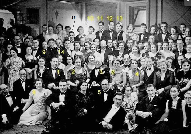
- The picture at the top of the article is of the Baird Television Ltd. staff dinner on March 18 1938. Those numbered are 3. Sir Harry Greer, 5. Captain West, 9. Ben Clapp, 10. Mary Tomes, 11. Gilbert Tomes, 12. Alfred Sommer, 13. Rosemary Sommer, 14. T.M.C.Lance, 15. Jan Forman (?).